$ 92.00 – $ 910.80
| Item | Specifications | |||||||||||||
|---|---|---|---|---|---|---|---|---|---|---|---|---|---|---|
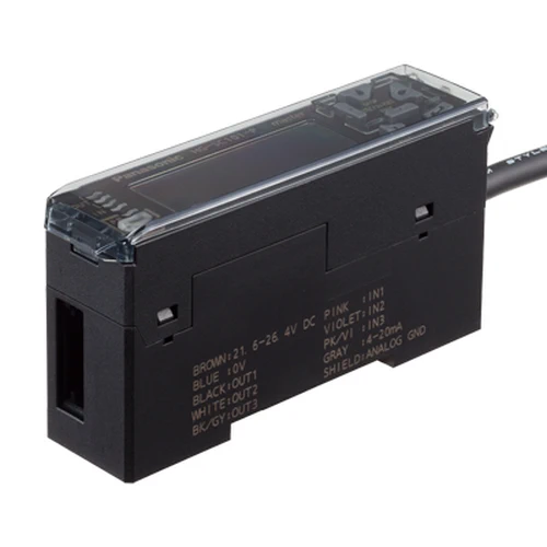
| Product Number | HG-TC113 | |||||||||||||
| Part Number | HG-TC113 | |||||||||||||
| Products Name | Controller | |||||||||||||
| Product details | Slave unit / Wire-saving type | |||||||||||||
| Applicable regulations | CE Marking (EMC Directive, RoHS Directive), UKCA Marking (EMC Regulations, RoHS Regulations) | |||||||||||||
| Pollution degree | 2 | |||||||||||||
| Operating altitude | 2,000 m 6561.68 ft or less (Note) : Do not use or store in an environment that has been pressurized to an air pressure higher than the atmospheric pressure at 0 m. |
|||||||||||||
| Environmental resistance : Protection | IP40(IEC) | |||||||||||||
| Environmental resistance : Ambient temperature | -10 to +50 ℃ +14 to +122 ℉ (No dew condensation or icing allowed) (Note), Storage: -20 to +60 ℃ -4 to +140 ℉ (Note) : When slave units are connected to the master unit, the maximum sink current / source current of control output and ambient temperature vary depending on the number of connected slave units as shown below.
scroll
scroll
scroll
|
|||||||||||||
| Environmental resistance : Ambient humidity | 35 to 85 % RH, Storage: 35 to 85 % RH | |||||||||||||
| Environmental resistance : Voltage withstandability | 1,000 V AC for one minute between all supply terminals connected together and enclosure | |||||||||||||
| Environmental resistance : Insulation resistance | 20 MΩ, or more, with 250 V DC megger between all supply terminals connected together and enclosure | |||||||||||||
| Environmental resistance : Vibration resistance | 10 to 150 Hz frequency, 0.75 mm 0.030 in double amplitude (10 to 58 Hz), Maximum acceleration 49 m/s2 (58 to 150 Hz) in X, Y and Z directions for two hours each | |||||||||||||
| Environmental resistance : Shock resistance | 98m/s2 acceleration (10 G approx.) in X, Y and Z directions five times each | |||||||||||||
| Material | Case: Polycarbonate, Cover: Polycarbonate, Switches: Polyacetal | |||||||||||||
| Cable | 0.2 mm2 2-core (brown and blue lead wires) / 0.15 mm2 7-core composite cable, 2 m 6.562 ft long | |||||||||||||
| Net weight | 60 g approx. | |||||||||||||
| Applicable sensor head | HG-T1010、HG-T1110 | |||||||||||||
| Maximum number of connectable controllers | Up to 15 slave units can be connected to a master unit. (Note) : When connected to a communication unit for digital displacement sensor, up to 14 slave units can be connected per master unit. |
|||||||||||||
| Supply voltage | 24 V DC ±10 %, including ripple 0.5 V (P-P) | |||||||||||||
| Current consumption | 100 mA or less (when sensor head is connected) (Note) : Current consumption does not include analog current output. |
|||||||||||||
| Sampling rate | 1 ms (standard sampling) / 0.5 ms (high-speed sampling) | |||||||||||||
| Average count (response time) | 1 time (2 ms), 2 times (3 ms), 4 times (5 ms), 8 times (9 ms), 16 times (17 ms), 32 times (33 ms), 64 times (65 ms), 128 times (129 ms), 256 times (257 ms), 512 times (513 ms), and 1,024 times (1,025 ms) switching type (Note) : Average count (response time) is for when the sampling cycle is set to 1 ms (standard sampling). Response times differ when the sampling cycle is set to 0.5 ms (high-speed sampling). |
|||||||||||||
| Display resolution | 1 μm 0.039 mil | |||||||||||||
| Display range | -199.999 to 199.999 mm -7.874 to 7.874 in | |||||||||||||
| Item | Specifications |
|---|---|
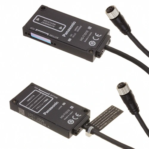
| Product Number | HG-T1010 |
| Part Number | HG-T1010 |
| Products Name | Sensor heads |
| Product details | Measurement width 10 mm 0.394 in / Standard type |
| Applicable regulations | CE Marking (EMC Directive, RoHS Directive), UKCA Marking (EMC Regulations, RoHS Regulations), FDA regulations |
| Applicable controller | HG-TC101 (-P), HG-TC111 (-P), HG-TC113 |
| Position detection method | CMOS-based |
| Installation distance | 0 to 500 mm 0 to 19.685 in [When side view attachment HG-TSV10 is attached, 0 to 100 mm 0 to 3.937 in (typical)] |
| Measurement width | 10 mm 0.394 in |
| Light source | Red semiconductor laser: Class 1 [IEC / EN / JIS / GB / KS / FDA] (Note)This product complies with the FDA regulations (FDA 21 CFR 1040.10 and 1040.11) in accordance with FDA Laser Notice No. 56, except for complying with IEC 60825-1 Ed. 3. |
| Repeatability | 1 μm 0.039 mil (Installation distance: 20 mm 0.787 in) 2.5 μm 0.098 mil (Installation distance: 100 mm 3.937 in) 5 μm 0.197 mil (Installation distance: 500 mm 19.685 in) (Note)This is the P-P value of digital measurement value with half shading at the middle position of the installation distance. |
| Linearity | ±0.12 % F.S. (Installation distance: 20 mm 0.787 in) ±0.28 % F.S. (Installation distance: 100 mm 3.937 in) (Note)Indicates an error with the ideal straight line of digital measured values. |
| Min. sensing object | ø0.5 mm ø0.020 in (Installation distance: 500 mm 19.685 in) (Note)When the light is blocked at the center position of 500 mm 19.685 in installation distance. |
| Temprerature characteristics | ±0.03 % F.S./℃ (Note)When the light is half-blocked at the center position of 100 mm 3.937 in installation distance. |
| Operation indicator | Emitter : Laser radiation indicator (Green) Receiver : Beam axis adjustment indicator (Orange / Green), Judgment output indicator (Orange / Green) |
| Pollution degree | 2 |
| Operating altitude | 2,000 m 6,561.68 ft or less (Note)Do not use or store in an environment that has been pressurized to an air pressure higher than the atmospheric pressure at 0 m. |
| Environmental resistance : Protection | IP67 (IEC) (Excluding connectors) |
| Environmental resistance : Ambient temperature | -10 to +45 ℃ +14 to +113 ℉ (No dew condensation or icing allowed), Storage: -20 to +60 ℃ -4 to +140 ℉ |
| Environmental resistance : Ambient humidity | 35 to 85 % RH, Storage: 35 to 85 % RH |
| Environmental resistance : Ambient illuminance | Incandescent light: 5,000 ℓx or less at the light-receiving face (Note)When the sampling cycle of the controller is set to “standard sampling”. |
| Environmental resistance : Insulation resistance | 20 MΩ or higher, using 250 V DC megger (between all terminals and case) |
| Environmental resistance : Vibration resistance | 10 to 55 Hz frequency, 1.5 mm 0.059 in double amplitude in X, Y and Z directions for two hours each |
| Environmental resistance : Shock resistance | 196 m/s2 acceleration in X, Y and Z directions three times each |
| Grounding method | Capacitor grounding |
| Material | Case: Die-cast aluminum, Light emitting and light receiving surfaces: Glass |
| Cable | 0.2 m 0.656 ft 4-core shielded cable with round connectors |
| Net weight | Emitter: 30 g approx., Receiver: 30 g approx. |
| Item | Specifications | |||||||||||||
|---|---|---|---|---|---|---|---|---|---|---|---|---|---|---|
| Product Number | HG-TC101 | |||||||||||||
| Part Number | HG-TC101 | |||||||||||||
| Products Name | Controller | |||||||||||||
| Product details | Master unit / High performance type | |||||||||||||
| Applicable regulations | CE Marking (EMC Directive, RoHS Directive), UKCA Marking (EMC Regulations, RoHS Regulations) | |||||||||||||
| Pollution degree | 2 | |||||||||||||
| Operating altitude | 2,000 m 6561.68 ft or less (Note) : Do not use or store in an environment that has been pressurized to an air pressure higher than the atmospheric pressure at 0 m. |
|||||||||||||
| Environmental resistance : Protection | IP40(IEC) | |||||||||||||
| Environmental resistance : Ambient temperature | -10 to +50 ℃ +14 to +122 ℉ (No dew condensation or icing allowed) (Note), Storage: -20 to +60 ℃ -4 to +140 ℉ (Note) : When slave units are connected to the master unit, the maximum sink current / source current of control output and ambient temperature vary depending on the number of connected slave units as shown below.
scroll
scroll
scroll
|
|||||||||||||
| Environmental resistance : Ambient humidity | 35 to 85 % RH, Storage: 35 to 85 % RH | |||||||||||||
| Environmental resistance : Voltage withstandability | 1,000 V AC for one minute between all supply terminals connected together and enclosure | |||||||||||||
| Environmental resistance : Insulation resistance | 20 MΩ, or more, with 250 V DC megger between all supply terminals connected together and enclosure | |||||||||||||
| Environmental resistance : Vibration resistance | 10 to 150 Hz frequency, 0.75 mm 0.030 in double amplitude (10 to 58 Hz), Maximum acceleration 49 m/s2 (58 to 150 Hz) in X, Y and Z directions for two hours each | |||||||||||||
| Environmental resistance : Shock resistance | 98m/s2 acceleration (10 G approx.) in X, Y and Z directions five times each | |||||||||||||
| Material | Case: Polycarbonate, Cover: Polycarbonate, Switches: Polyacetal | |||||||||||||
| Cable | 0.2 mm2 2-core (brown and blue lead wires) / 0.15 mm2 7-core composite cable, 2 m 6.562 ft long | |||||||||||||
| Net weight | 140 g approx. | |||||||||||||
| Applicable sensor head | HG-T1010、HG-T1110 | |||||||||||||
| Maximum number of connectable controllers | Up to 15 slave units can be connected to a master unit. (Note) : When connected to a communication unit for digital displacement sensor, up to 14 slave units can be connected per master unit. |
|||||||||||||
| Supply voltage | 24 V DC ±10 %, including ripple 0.5 V (P-P) | |||||||||||||
| Current consumption | 100 mA or less (when sensor head is connected) (Note) : Current consumption does not include analog current output. |
|||||||||||||
| Analogue output : Analog voltage output | •Voltage output range: 1 to 5 V/F.S. (default value) •Linearity: ±0.05 % F.S. •Output when alarm occurs: 5.2 V •Output impedance: 100 Ω max. (Note) : Linearity is a value calculated from digitally measured values at F.S. = 16 mA for current output or F.S. = 4 V for voltage output. |
|||||||||||||
| Analogue output : Analog current output | •Current output range: 4 to 20 mA/F.S. (default value) •Linearity: ±0.25 % F.S. •Output when alarm occurs: 0 mA •Load impedance: 250 Ω max. (Note) : Linearity is a value calculated from digitally measured values at F.S. = 16 mA for current output or F.S. = 4 V for voltage output. |
|||||||||||||
| Control output(Output 1, Output 2, Output 3) | NPN open-collector transistor •Maximum sink current: 50 mA (Note) •Applied voltage: 30 V DC or less (between output and 0 V) •Residual voltage: 1.5 V or less (at 50 mA sink current) •Leakage current: 0.1 mA or less PNP open-collector transistor (Note) : When slave units are connected to the master unit, the maximum sink current / source current of control output and ambient temperature vary depending on the number of connected slave units as shown below.
scroll
scroll
scroll
|
|||||||||||||
| Control output(Output 1, Output 2, Output 3) : Short-circuit protection | Incorporated (automatic reset type) | |||||||||||||
| Control output(Output 1, Output 2, Output 3) : Judgment output | N.O. / N.C. switching type | |||||||||||||
| Control output(Output 1, Output 2, Output 3) : Alarm output | Open when alarm occurs | |||||||||||||
| External output switching | Output 1, Output 2, and Output 3 can be switched to 3-value, 2-value, Logic, and Logic 2. | |||||||||||||
| External input(Input 1, Input 2, Input 3) |
Non-contact input or NPN open-collector transistor •Input conditions Invalid: +8 V to +V DC or open, Valid: 0 to +1.2 V DC •Input impedance: 10 kΩ approx. Non-contact input or PNP open-collector transistor |
|||||||||||||
| External input(Input 1, Input 2, Input 3) : Input time | • Trigger input: 2 ms or more (ON) • Laser emission stop input, preset input, reset input, bank input A/B(Note): 20 ms or more (ON) (Note) : Average count (response time) is for when the sampling cycle is set to 1 ms (standard sampling). Response times differ when the sampling cycle is set to 0.5 ms (high-speed sampling). |
|||||||||||||
| External input switching | Input 1, Input 2, and Input 3 can be switched to “Preset / Reset / Trigger”, “Bank Input A / Bank Input B / Select (Preset, Reset, Trigger)”, or “Laser emission stop”. | |||||||||||||
| Sampling rate | 1 ms (standard sampling) / 0.5 ms (high-speed sampling) | |||||||||||||
| Average count (response time) | 1 time (2 ms), 2 times (3 ms), 4 times (5 ms), 8 times (9 ms), 16 times (17 ms), 32 times (33 ms), 64 times (65 ms), 128 times (129 ms), 256 times (257 ms), 512 times (513 ms), and 1,024 times (1,025 ms) switching type (Note) : Average count (response time) is for when the sampling cycle is set to 1 ms (standard sampling). Response times differ when the sampling cycle is set to 0.5 ms (high-speed sampling). |
|||||||||||||
| Display resolution | 1 μm 0.039 mil | |||||||||||||
| Display range | -199.999 to 199.999 mm -7.874 to 7.874 in | |||||||||||||
| Interference prevention function | Incorporated (Note) : This function operates for each set of 4 connected controllers. |
|||||||||||||
| Item | Specifications |
|---|---|
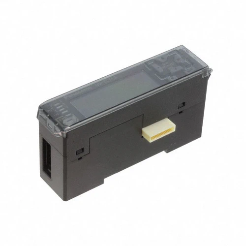
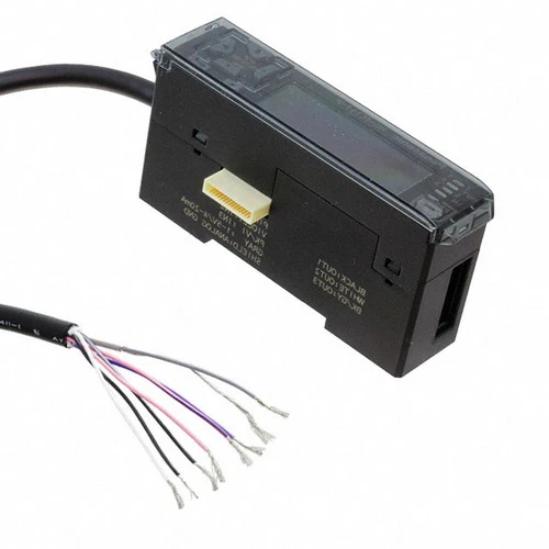
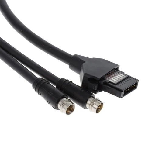
| Product Number | CN-HT-C2 |
| Part Number | CN-HT-C2 |
| Products Name | Sensor head connection cables |
| Product details | Cable length 2 m 6.562 ft |
| Item | Specifications | |||||||||||||
|---|---|---|---|---|---|---|---|---|---|---|---|---|---|---|
| Product Number | HG-TC111 | |||||||||||||
| Part Number | HG-TC111 | |||||||||||||
| Products Name | Controller | |||||||||||||
| Product details | Slave unit / High performance type | |||||||||||||
| Applicable regulations | CE Marking (EMC Directive, RoHS Directive), UKCA Marking (EMC Regulations, RoHS Regulations) | |||||||||||||
| Pollution degree | 2 | |||||||||||||
| Operating altitude | 2,000 m 6561.68 ft or less (Note) : Do not use or store in an environment that has been pressurized to an air pressure higher than the atmospheric pressure at 0 m. |
|||||||||||||
| Environmental resistance : Protection | IP40(IEC) | |||||||||||||
| Environmental resistance : Ambient temperature | -10 to +50 ℃ +14 to +122 ℉ (No dew condensation or icing allowed) (Note), Storage: -20 to +60 ℃ -4 to +140 ℉ (Note) : When slave units are connected to the master unit, the maximum sink current / source current of control output and ambient temperature vary depending on the number of connected slave units as shown below.
scroll
scroll
scroll
|
|||||||||||||
| Environmental resistance : Ambient humidity | 35 to 85 % RH, Storage: 35 to 85 % RH | |||||||||||||
| Environmental resistance : Voltage withstandability | 1,000 V AC for one minute between all supply terminals connected together and enclosure | |||||||||||||
| Environmental resistance : Insulation resistance | 20 MΩ, or more, with 250 V DC megger between all supply terminals connected together and enclosure | |||||||||||||
| Environmental resistance : Vibration resistance | 10 to 150 Hz frequency, 0.75 mm 0.030 in double amplitude (10 to 58 Hz), Maximum acceleration 49 m/s2 (58 to 150 Hz) in X, Y and Z directions for two hours each | |||||||||||||
| Environmental resistance : Shock resistance | 98m/s2 acceleration (10 G approx.) in X, Y and Z directions five times each | |||||||||||||
| Material | Case: Polycarbonate, Cover: Polycarbonate, Switches: Polyacetal | |||||||||||||
| Cable | 0.15 mm2 7-core composite cable, 2 m 6.562 ft long | |||||||||||||
| Net weight | 140 g approx. | |||||||||||||
| Applicable sensor head | HG-T1010、HG-T1110 | |||||||||||||
| Maximum number of connectable controllers | Up to 15 slave units can be connected to a master unit. (Note) : When connected to a communication unit for digital displacement sensor, up to 14 slave units can be connected per master unit. |
|||||||||||||
| Supply voltage | 24 V DC ±10 %, including ripple 0.5 V (P-P) | |||||||||||||
| Current consumption | 100 mA or less (when sensor head is connected) (Note) : Current consumption does not include analog current output. |
|||||||||||||
| Analogue output : Analog voltage output | •Voltage output range: 1 to 5 V/F.S. (default value) •Linearity: ±0.05 % F.S. •Output when alarm occurs: 5.2 V •Output impedance: 100 Ω max. (Note) : Linearity is a value calculated from digitally measured values at F.S. = 16 mA for current output or F.S. = 4 V for voltage output. |
|||||||||||||
| Analogue output : Analog current output | •Current output range: 4 to 20 mA/F.S. (default value) •Linearity: ±0.25 % F.S. •Output when alarm occurs: 0 mA •Load impedance: 250 Ω max. (Note) : Linearity is a value calculated from digitally measured values at F.S. = 16 mA for current output or F.S. = 4 V for voltage output. |
|||||||||||||
| Control output(Output 1, Output 2, Output 3) | NPN open-collector transistor •Maximum sink current: 50 mA (Note) •Applied voltage: 30 V DC or less (between output and 0 V) •Residual voltage: 1.5 V or less (at 50 mA sink current) •Leakage current: 0.1 mA or less PNP open-collector transistor (Note) : When slave units are connected to the master unit, the maximum sink current / source current of control output and ambient temperature vary depending on the number of connected slave units as shown below.
scroll
scroll
scroll
|
|||||||||||||
| Control output(Output 1, Output 2, Output 3) : Short-circuit protection | Incorporated (automatic reset type) | |||||||||||||
| Control output(Output 1, Output 2, Output 3) : Judgment output | N.O. / N.C. switching type | |||||||||||||
| Control output(Output 1, Output 2, Output 3) : Alarm output | Open when alarm occurs | |||||||||||||
| External output switching | Output 1, Output 2, and Output 3 can be switched to 3-value, 2-value, Logic, and Logic 2. | |||||||||||||
| External input(Input 1, Input 2, Input 3) |
Non-contact input or NPN open-collector transistor •Input conditions Invalid: +8 V to +V DC or open, Valid: 0 to +1.2 V DC •Input impedance: 10 kΩ approx. Non-contact input or PNP open-collector transistor |
|||||||||||||
| External input(Input 1, Input 2, Input 3) : Input time | • Trigger input: 2 ms or more (ON) • Laser emission stop input, preset input, reset input, bank input A/B(Note): 20 ms or more (ON) (Note) : Average count (response time) is for when the sampling cycle is set to 1 ms (standard sampling). Response times differ when the sampling cycle is set to 0.5 ms (high-speed sampling). |
|||||||||||||
| External input switching | Input 1, Input 2, and Input 3 can be switched to “Preset / Reset / Trigger”, “Bank Input A / Bank Input B / Select (Preset, Reset, Trigger)”, or “Laser emission stop”. | |||||||||||||
| Sampling rate | 1 ms (standard sampling) / 0.5 ms (high-speed sampling) | |||||||||||||
| Average count (response time) | 1 time (2 ms), 2 times (3 ms), 4 times (5 ms), 8 times (9 ms), 16 times (17 ms), 32 times (33 ms), 64 times (65 ms), 128 times (129 ms), 256 times (257 ms), 512 times (513 ms), and 1,024 times (1,025 ms) switching type (Note) : Average count (response time) is for when the sampling cycle is set to 1 ms (standard sampling). Response times differ when the sampling cycle is set to 0.5 ms (high-speed sampling). |
|||||||||||||
| Display resolution | 1 μm 0.039 mil | |||||||||||||
| Display range | -199.999 to 199.999 mm -7.874 to 7.874 in | |||||||||||||
INOSAKI Limited
RM B 5/F Gaylord Comm,
Bldg 114-118 Lockhart Rd.
Hong Kong
INOSAKI Sdn. Bhd.
2-1-9, Ground Floor, One Square, Tingkat Mahsuri 1,
11900 Bayan Lepas, Penang
INOSAKI Pte. Ltd.
101 Upper Cross Street,
No. 06-17, People’s Park Centre,
Singapore (058357)